
|
| Home
Club Info Ideas & Builds Downloads Newbie Calendar Interclub Series |
SupraKuda
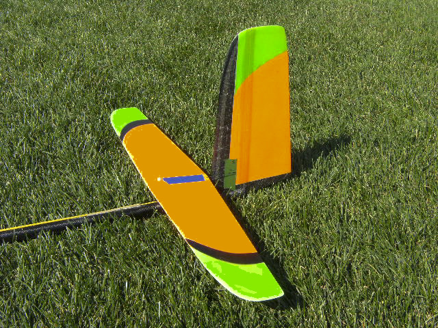
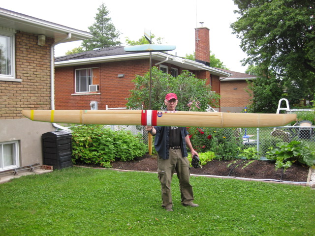
3.8 Kuda maiden flight! 20 June 2012 A new 3.8m Kuda has been successfully maiden at the MATS field. Duc has put together a very visible color scheme. There are no reasons to loose the sight of this beast far down wind...even in a hazy day!!! The model is characterised by some structural modifications tailored to improve manufacturability. A strip of pre-cured CF has been glued to the foam before bagging to ease the removal of the foam in the area where the spar is eventually installed. Secondary spar has been built "à la Drela" wrapping glass cloth around the foam prior to cure the kevlar skins. The finish is beautiful and obtained by painting the mylar before bagging. 
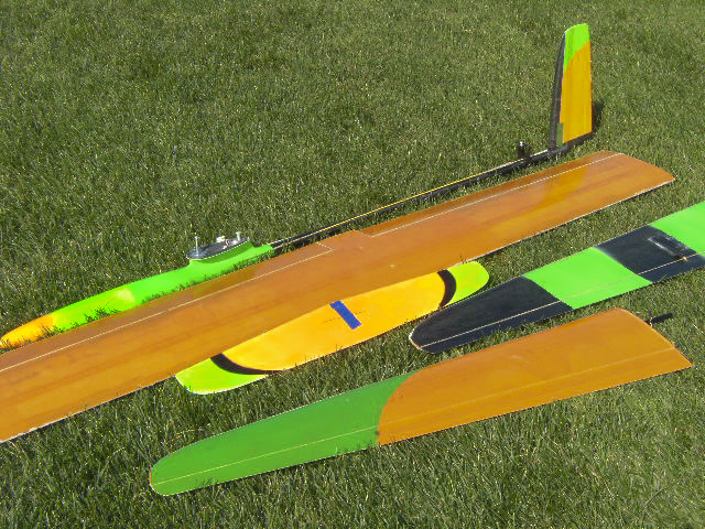
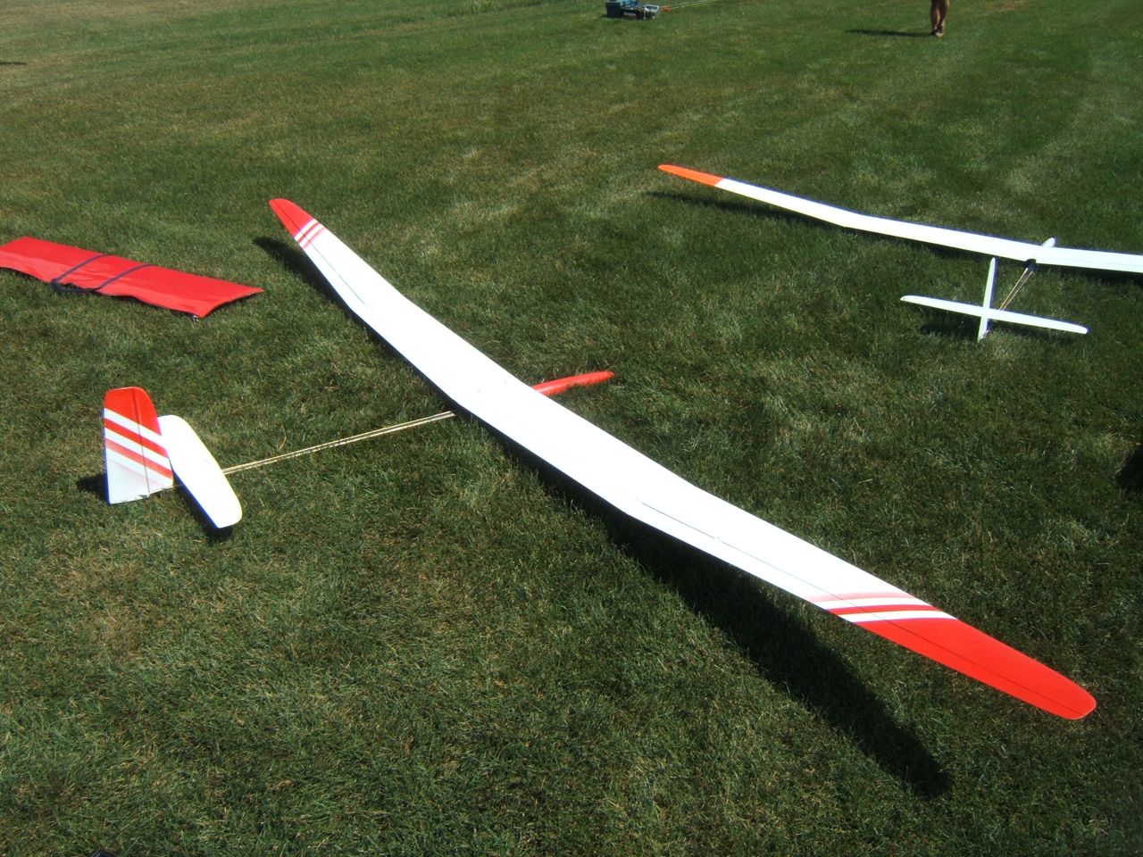
The experience collected while flying the first prototypes of the 4m Kuda has been put at the service of this first flight. Settings and CoG were transferred from previous models to the new ship, giving to Duc great confidence of the ability of the model to perform. And so it was. The CoG must be fine tuned, being a bit too forward. Same for the hook, being conservatively set at the most forward allowed position. A bit of work on those aspects and the model will be able to hit the road!!! Brakes have shown incredible authority while deflected to full 90 degrees down. The ship litterally stops mid air!!! Following this new test the Goliath (aka the first 90oz Kuda protoype) will be modified to give flaps full 90 degrees rotation! The model weights (including servos and wiring) are as follows: Fuselage RTF: 789 g Stabs: 46g Left tip with joiner rod: 296g Right tip with joiner rod: 307g Central panel: 999g Total weight 2437 g (86 oz). Kuda at the field August 2011 The Kudas have been flying since a while now. Both the first heavier version, surnamed Goliath, and the MK2 (10 ounces ligther than the first) have been proven during severalcompetitions. The pictures show the Goliath ready to fly before paint was applied to the wing and once finished with touches of red for better visibility. 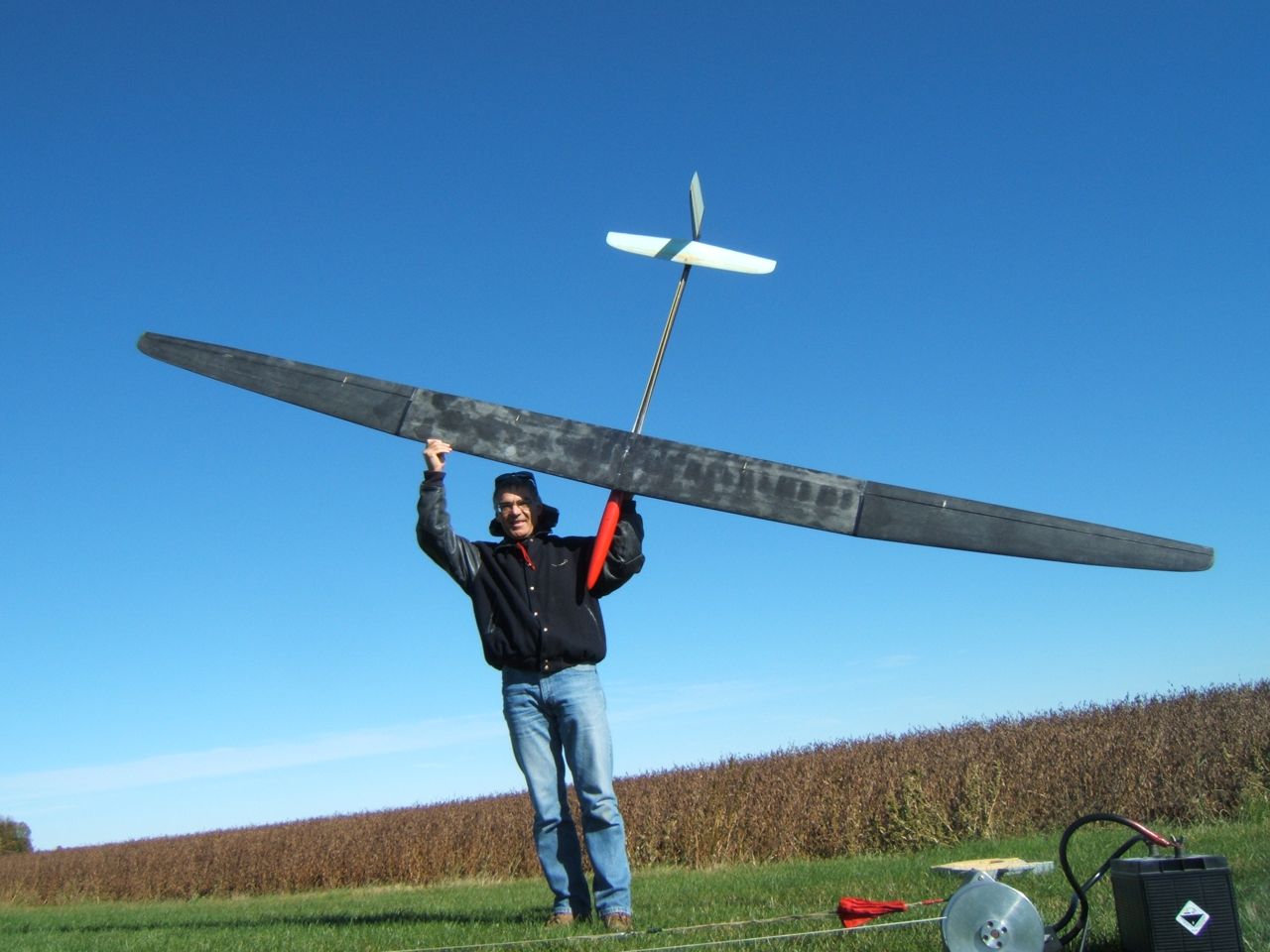
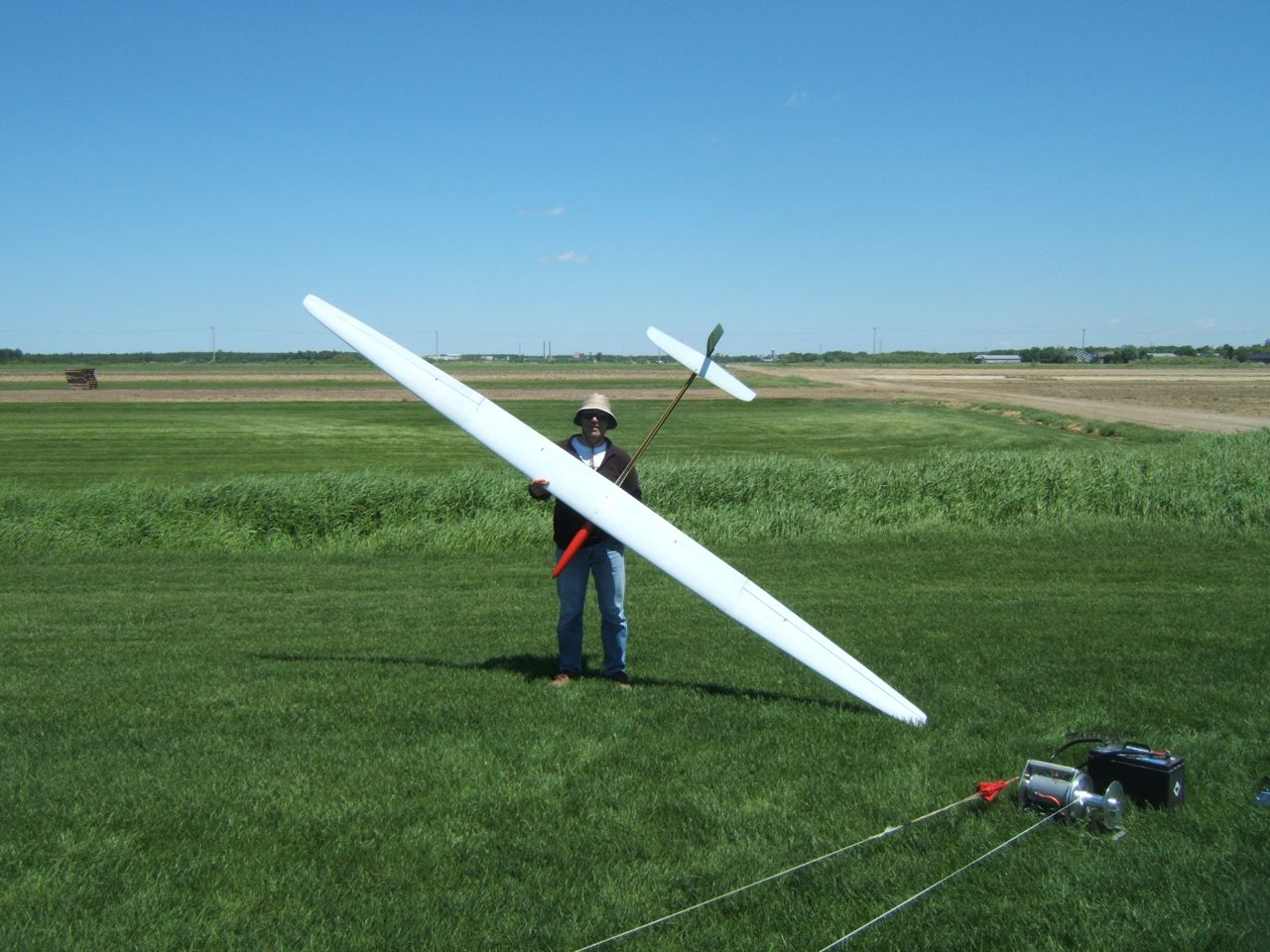 And here they are: on the left the MK2 with its light touch of paint. The orange tips are fluorescent and have been very useful when flying in stormy grey weather at great distance! On the left we have the Kuda Goliath ready to take the air. 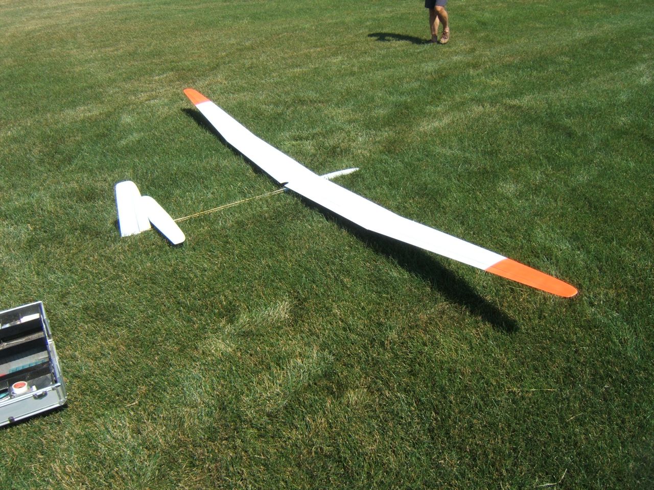
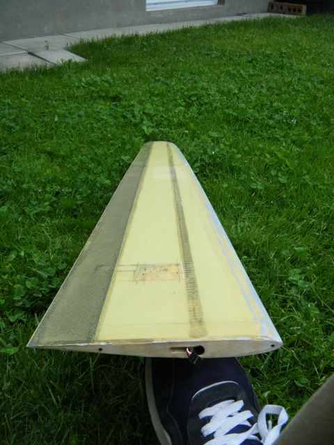
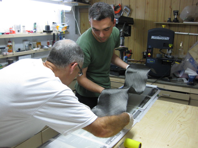
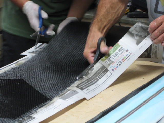
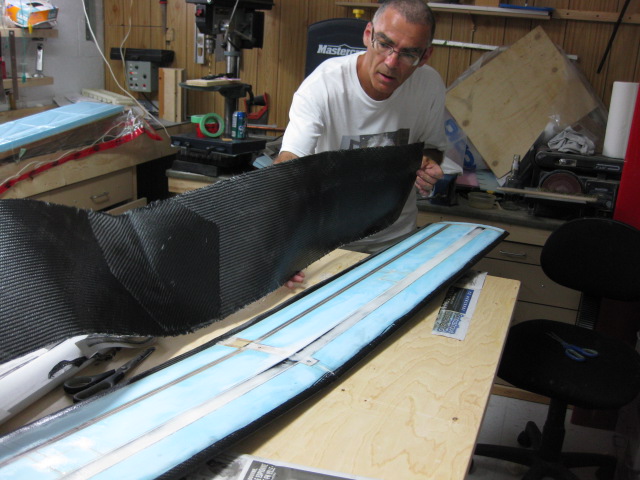
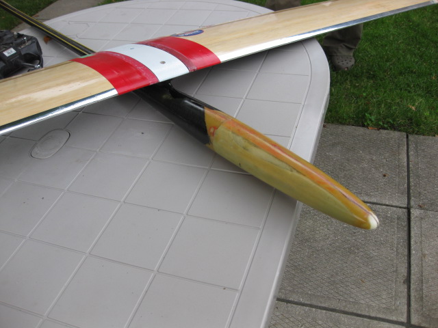
Kuda MK 2 23 May 2011 After many different flying sessions we came up with a list of improvements for the Kuda and we implemented them with the Kuda MK 2! The new glider features a brand new layup for the wings: other than the 3/4oz glass fiber as a surface finish layer, the skins are now entirely made up of 1 layer of kevlar 1.8 oz with the exception of the root region of the central panel where we have put 2 layers of kevlar and 1 extra layer of carbon 3 oz. Here's the model assembled for the first time with the wing right out of the bags! 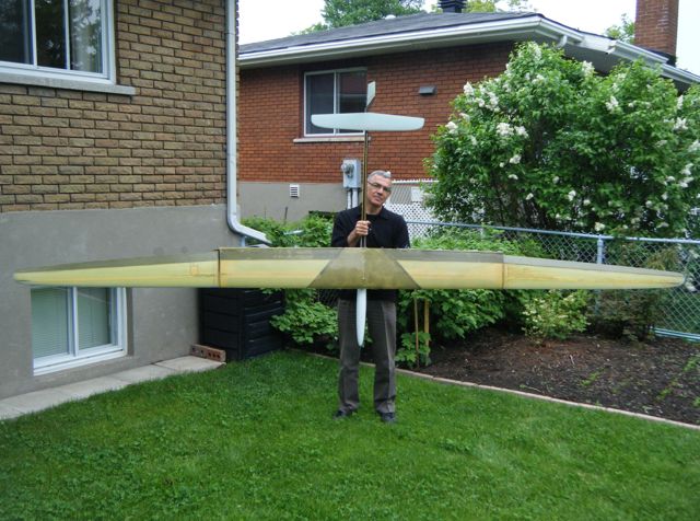 The wing tips are down to 10 oz and they are very stiff. The carbon reinforcements on the ailerons make up for a 100% flutter free movables! Have a look! 
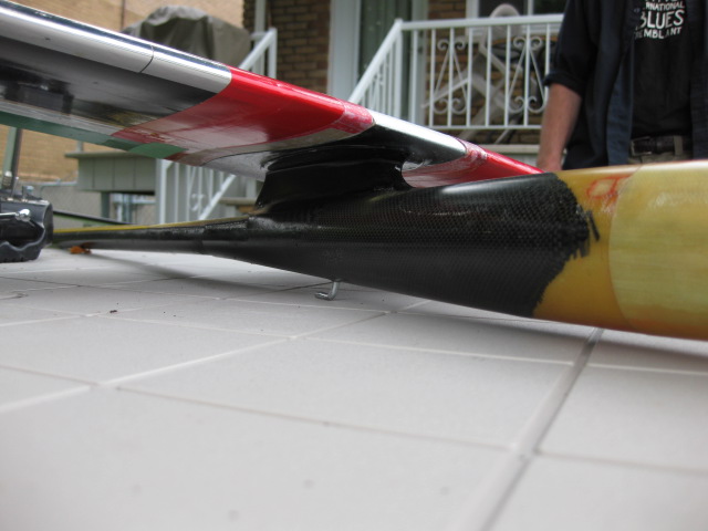
The last area of improvement was the fin attachment: the first prototype showed this as a weak spot. We proceeded in cutting a precise slot as per the airfoil of the fin in the boom, and bonded the fin through the boom. The result is outstanding: the boom is way stiffer in torsion than before, and the fin doesn't come off even with the worst landing! 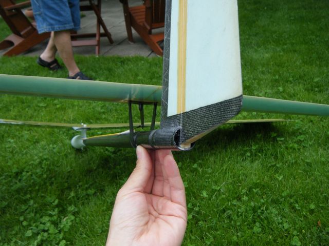
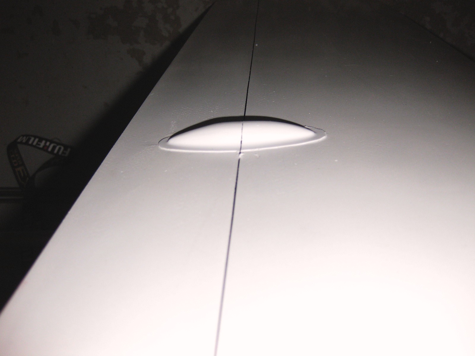
 Servo covers 13 May 2011 Steve and Jacques put together a little machine to heat form light plastic servo covers. The machine is built around a heat source and a home vacuum! Quick and simple...what more!?!? 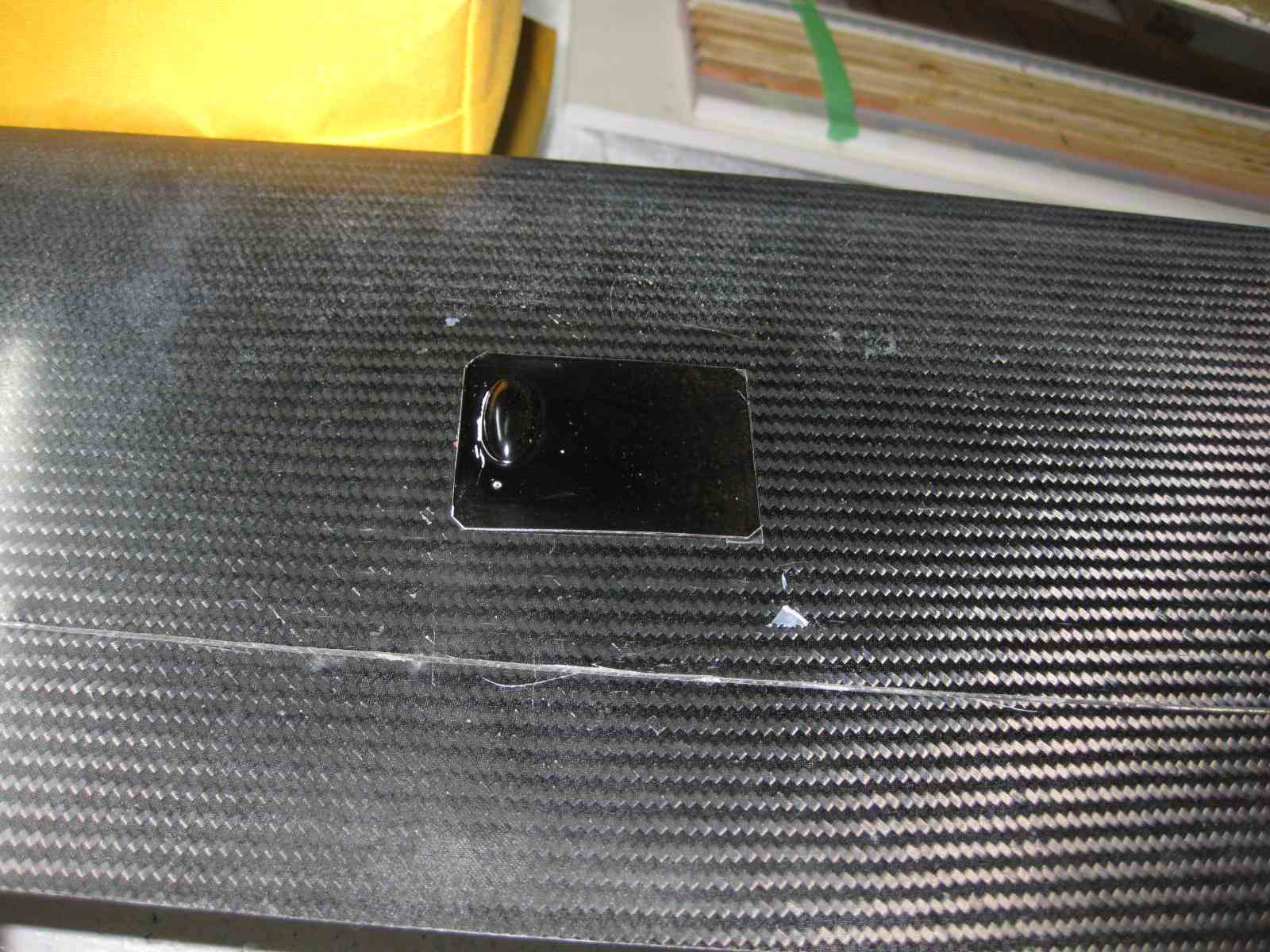
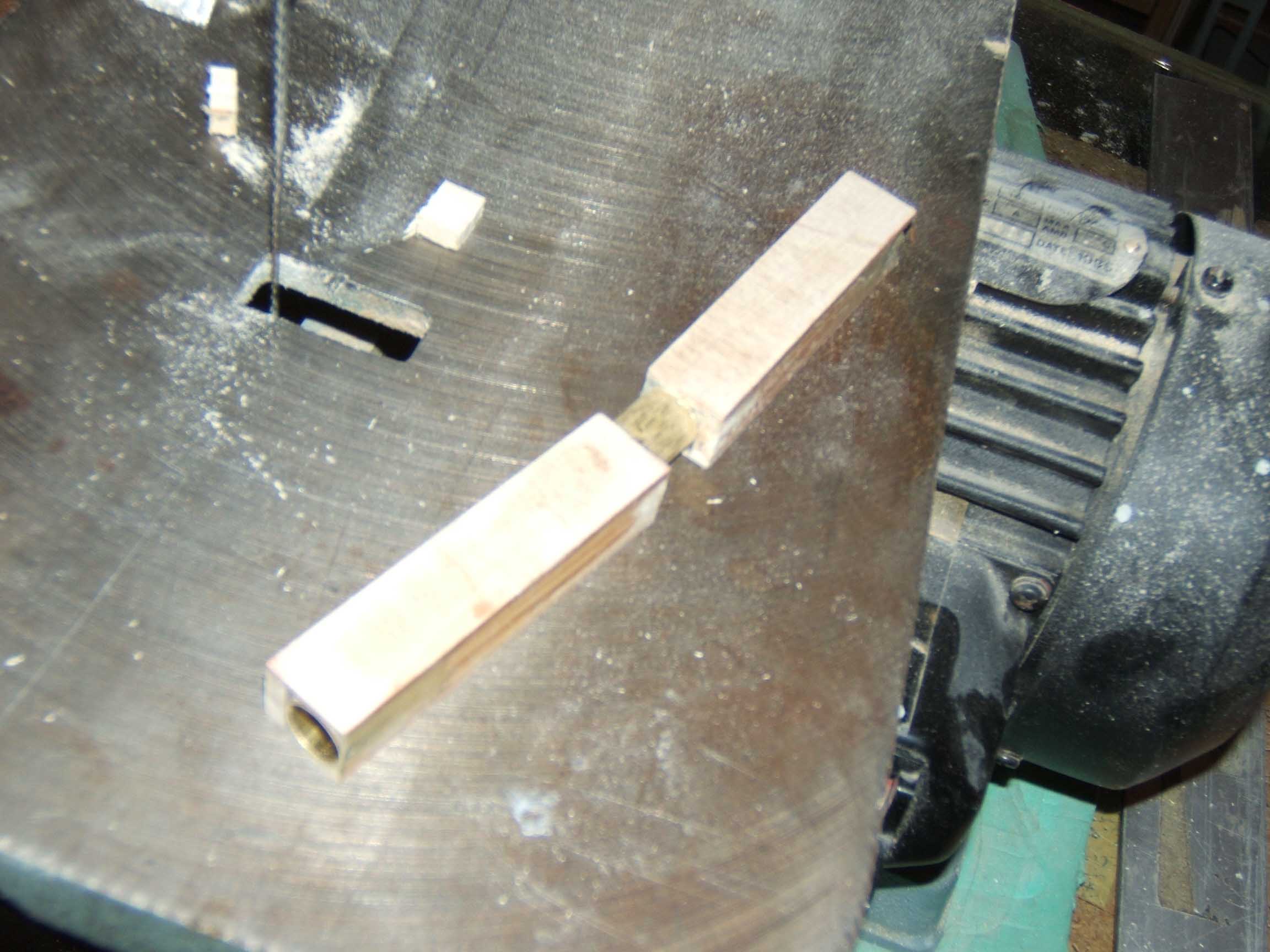
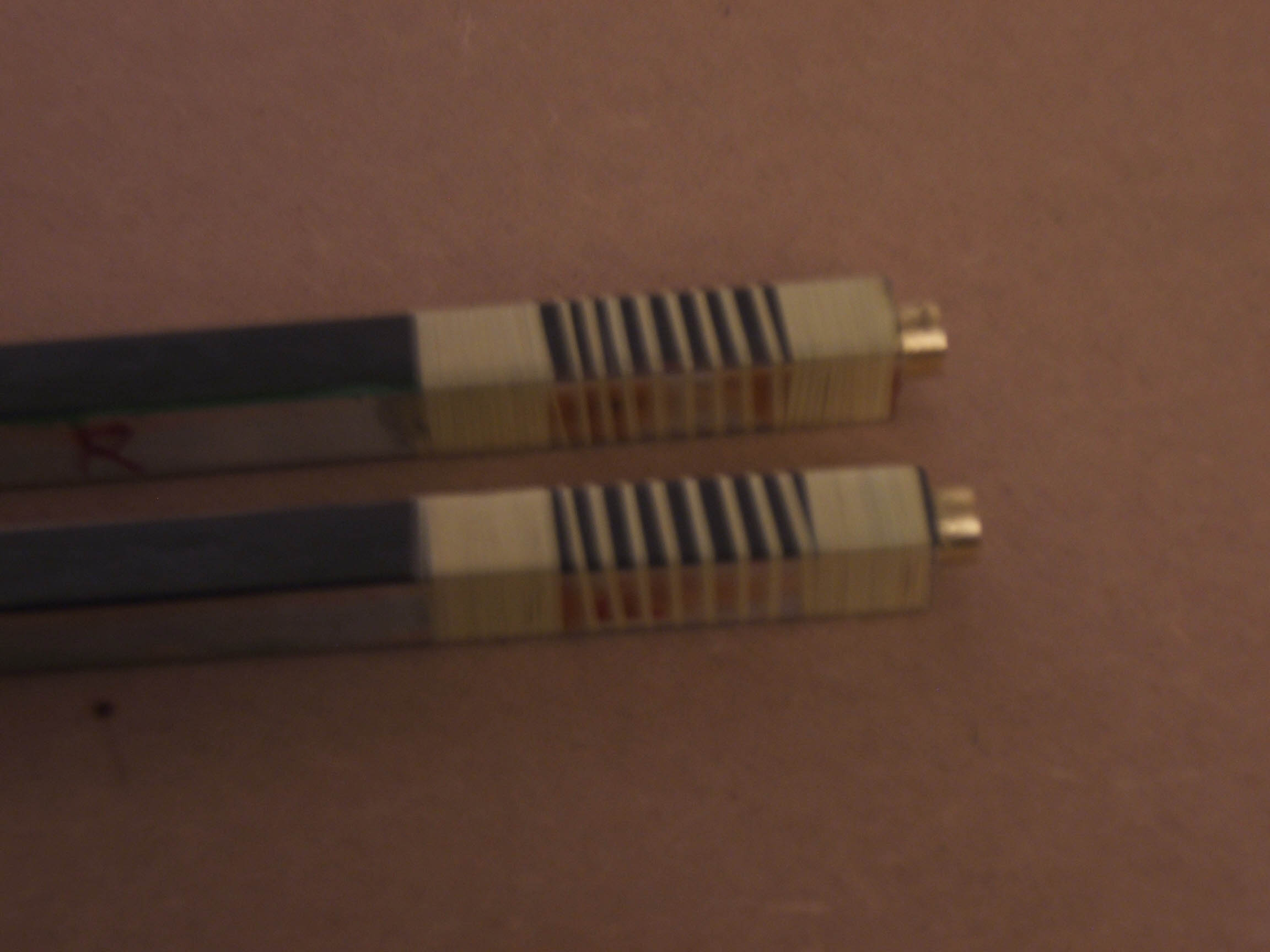
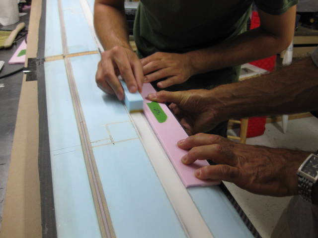
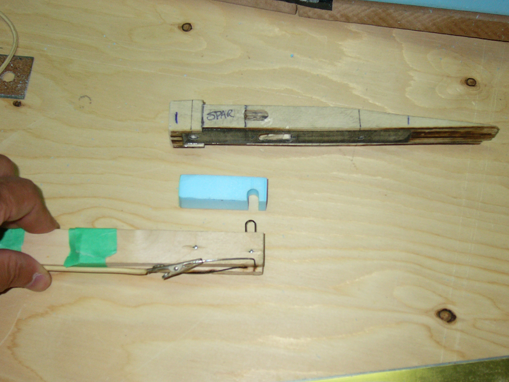
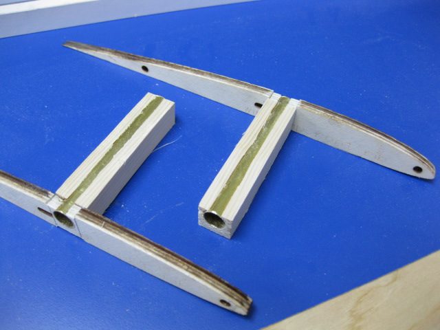
Tip spars August 2010 Central panel is done and now we focus on the Tips of our bird. Layup and spar are definitely lighter than the central ones. Here some pictures of the jig used to assemble the joiner box, which is a little puzzle of laser cut wooden triangles and a bit of brass tube. The jig guarantees the dihedral angle at each assembly. Then the box right before cutting and the finished spar with the box installed. 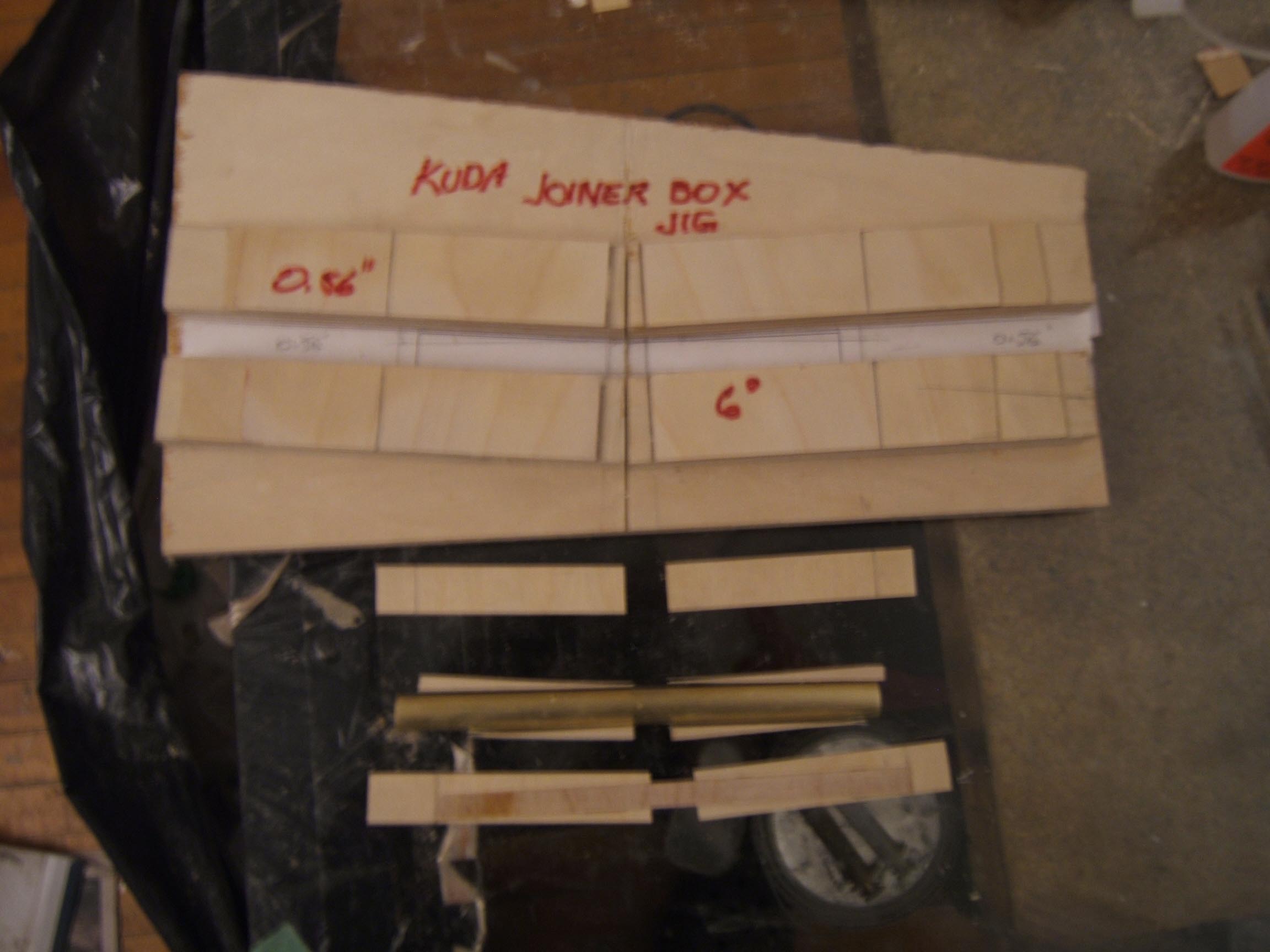
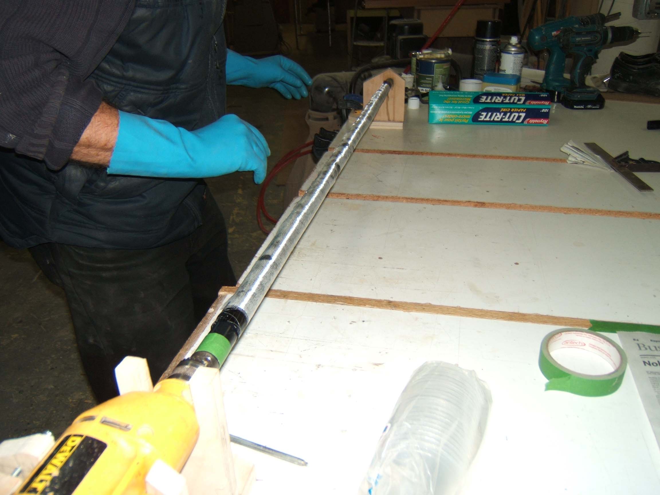
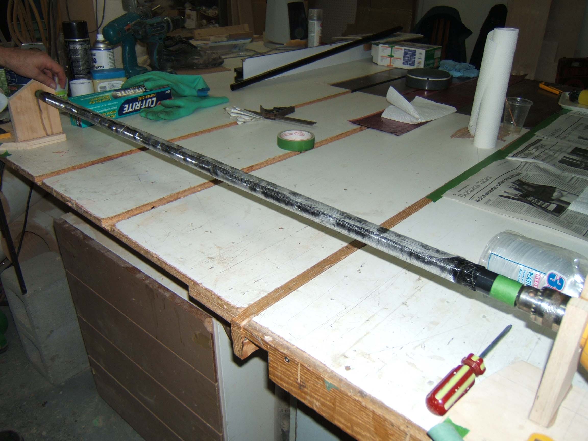
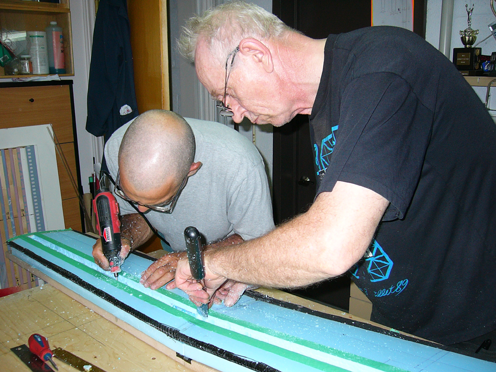
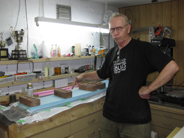
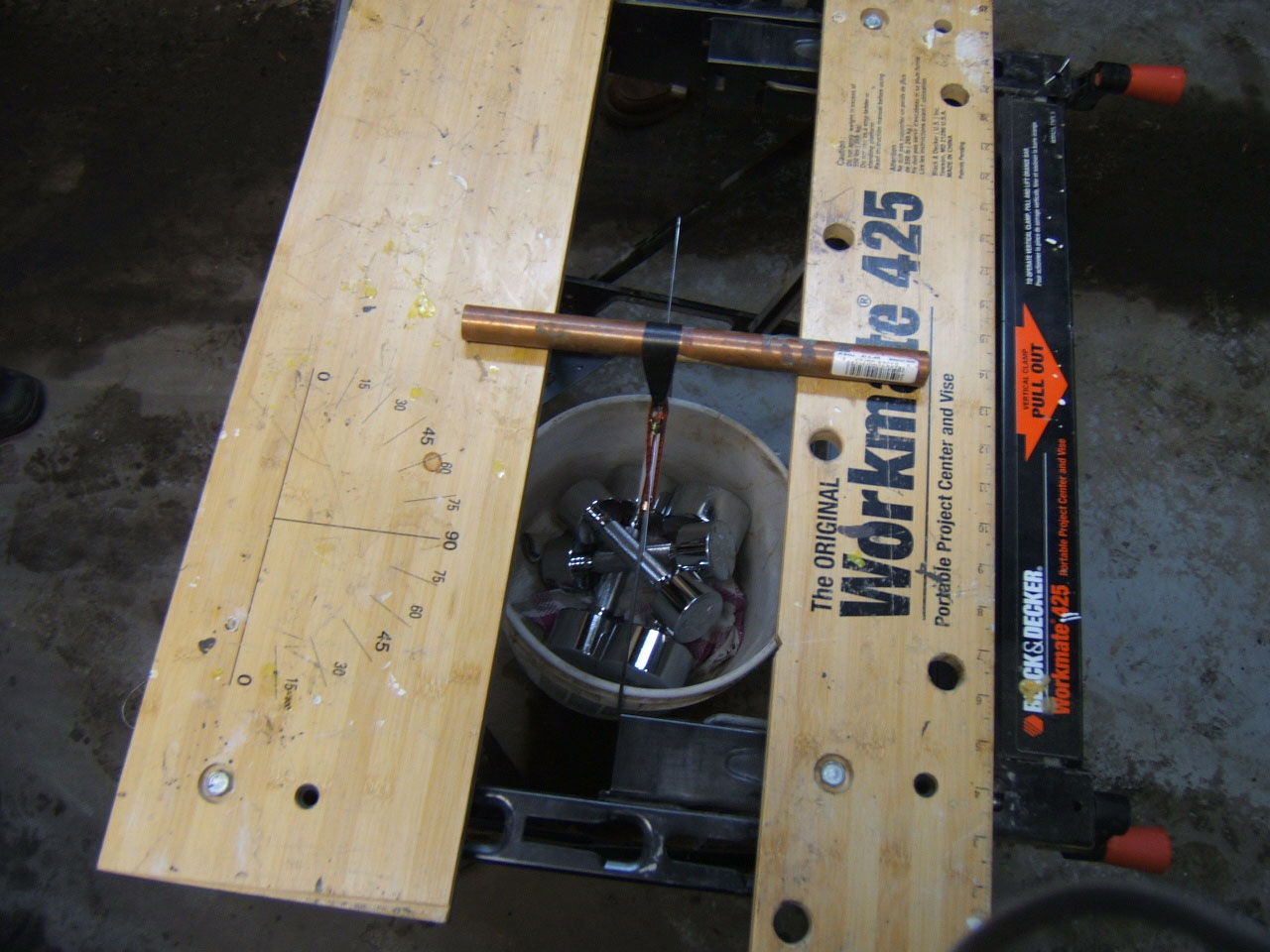
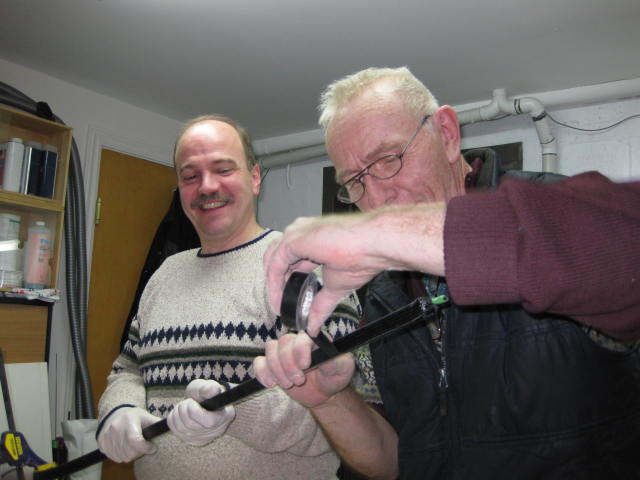
Rolling Booms Sometimes in the spare time during 2010 and nowadays whenever it is needed! After a few attempts with different de-moulding agents (first trials ended up with all sorts of bricks) and after having read the Babylonean amount of docs digged out from the Internet by our Master of Wisdom Duc, Steve and Jacques got the right recipe to roll booms on our own and the secret was revealed to the masses: put lots, lots and lots petroleum jelly on the mandrel and do not tighten too much the VHS tape at the end! EASY! 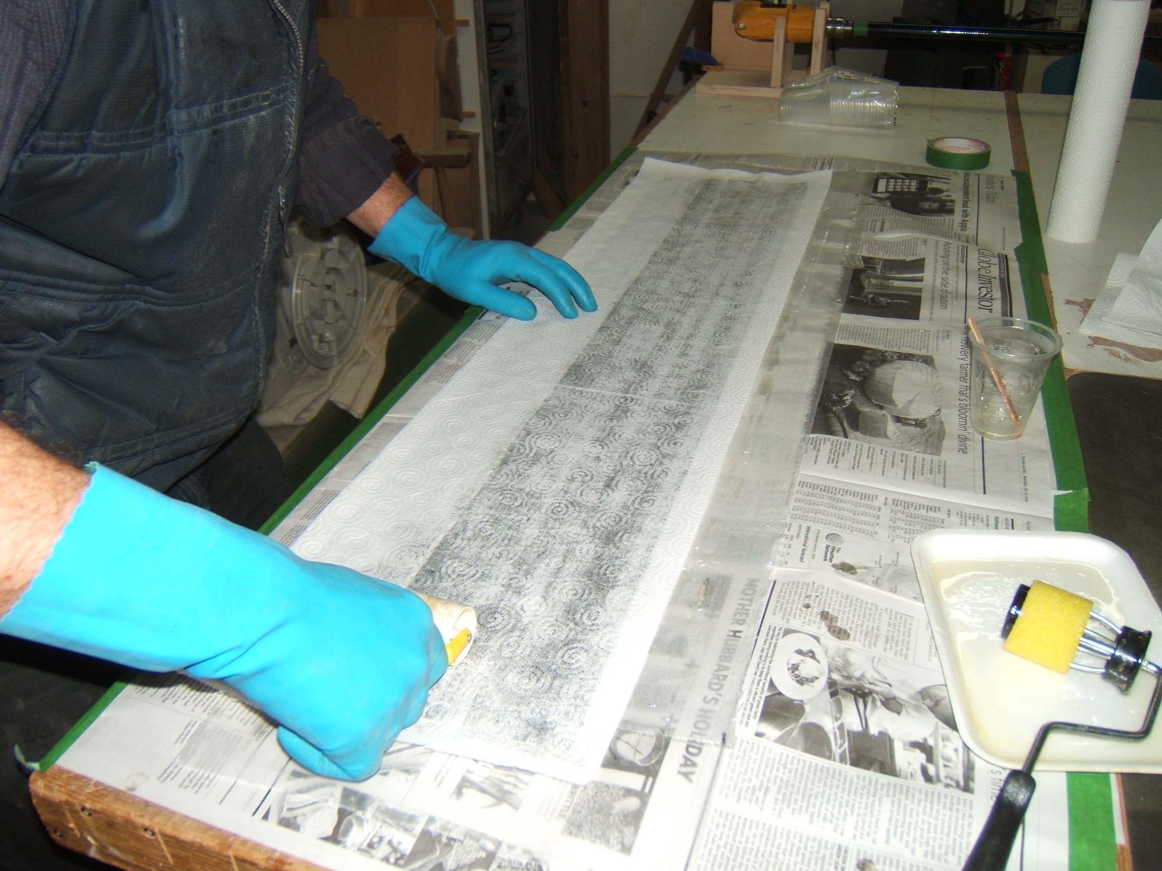

Wing Central Panel - Step 5 29 July 2010 First thing first, we cut the cloth plies and waxed (many many times) the mylars. Mylars are supposed to be incompatible with epoxy but around the edges you can have troubles therefore we decided to take no risk and wax them thoroughtly! 
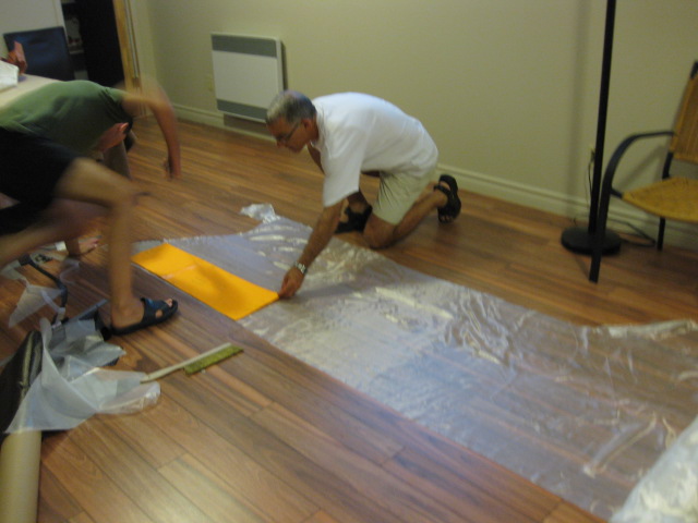
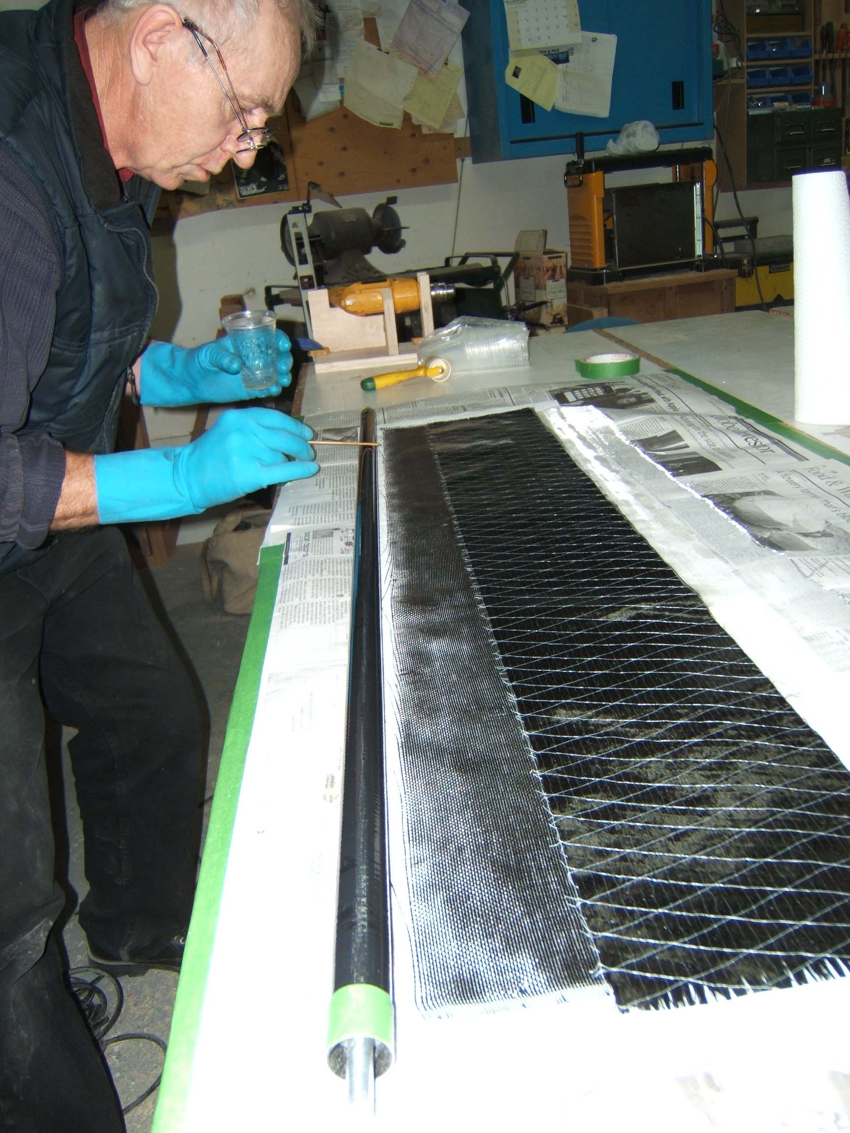
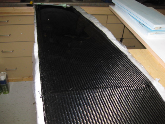
Time to layup the cloths. First the .25oz glass, very carefully with a light brush. This thing is so fin it can give real hard time when laying-up! Electrostatic charges are your friend here, helping you out to keep the cloth onto the mylar. Then it comes to the structural plies: 6oz carbon...way overkill, but so easy to layup and work with altogether! 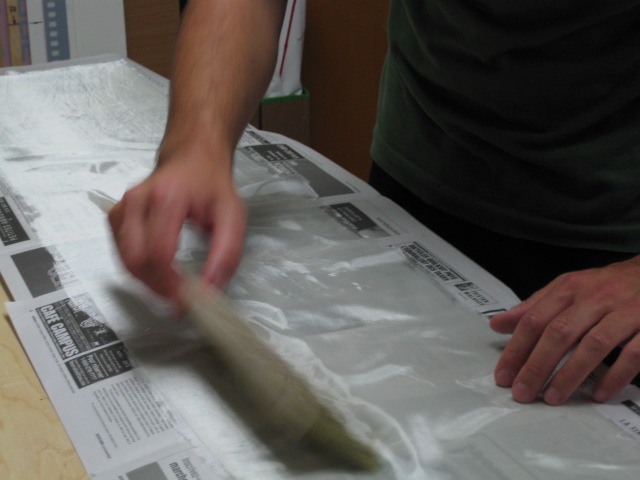


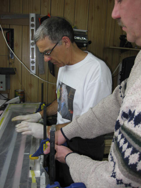
When the laminate is ready, we transfer it to the foam which has been wetted all around the edges, in the region of the main and secondary spar as well as the bolt beam area and tip ribs. When everything is in the right place, some tape is used to keep the whole thing together while we handle the vacuum bag. Careful here, the mylar is waxed and the tape doesn't want to stick anywhere!!! 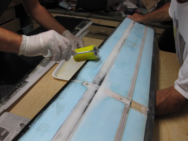
That's it, the wing is in the bag onto the MDF bed giving the right dihedral. One can't see this very well from this pics, we will add a specific picture of the gizmo soon! 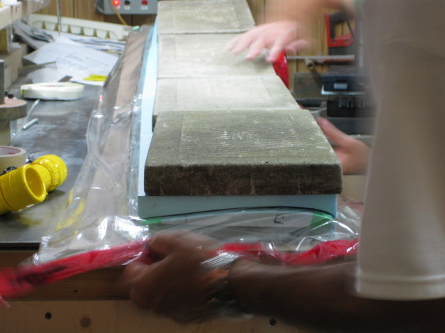
And here's the final result. Less perfect than the lower skin, but still very good!!! The temperature in the room was too high and the resin started gelling too soon. The dull regions you can see is where the fiberglass is not well bonded to the carbon. Stephen has injected manually some resin and sanded the whole thing to a perfect shiny finish. This wing is not going to bend at all...it is a monster of strength!!! 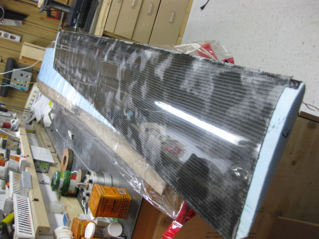

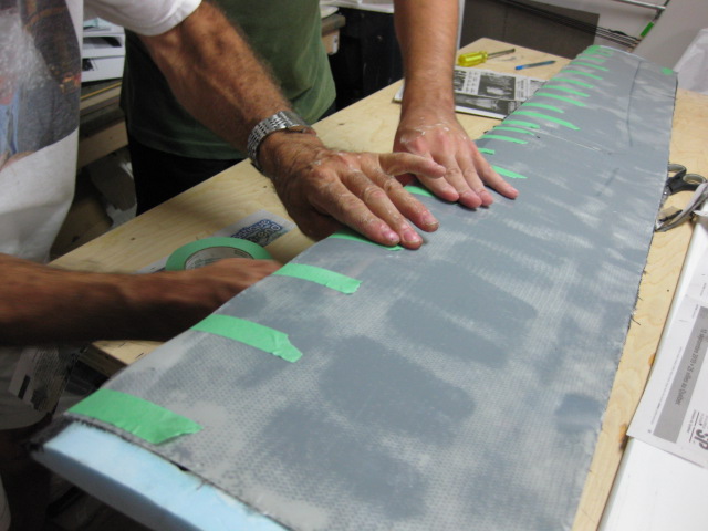
Wing Central Panel - Step 4 27 July 2010 When all the spars and ribs are glued in place the panel has to be sanded carefully before laying-up the upper skin. It is quite of a time consuming task! 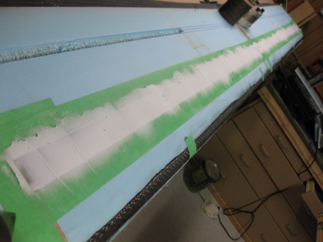
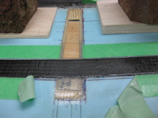
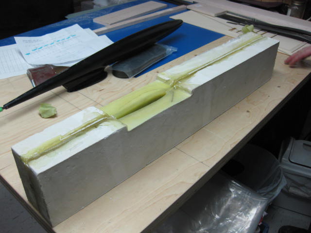
Wing Central Panel - Step 3 23 July 2010 The main spar has been glued in place. The secondary spar has been built: a sandwich of balsa, carbon cloth, foam, carbon cloth and balsa will be positioned corresponding to the aileron hinge. The foam will be removed after the final cure to leave the movable free to rotate and the two structural spars carbon faced. 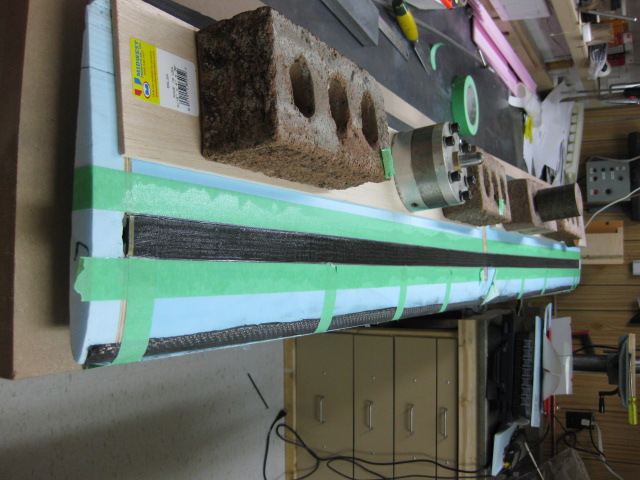
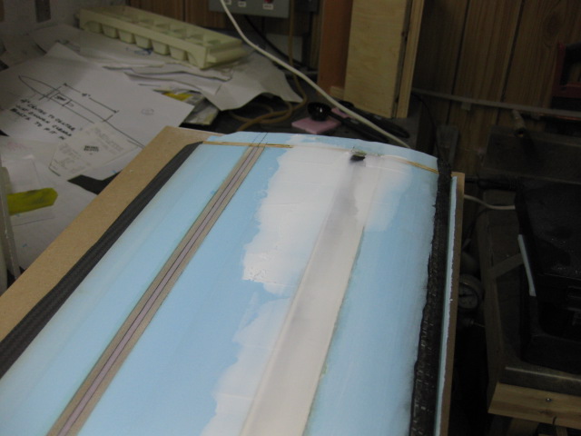
Wing central panel - Step 2 6 July 2010 The foam corresponding to the main spar location has been removed and a specific Jig has been built to route the harness for the radio gear close to the spar web. 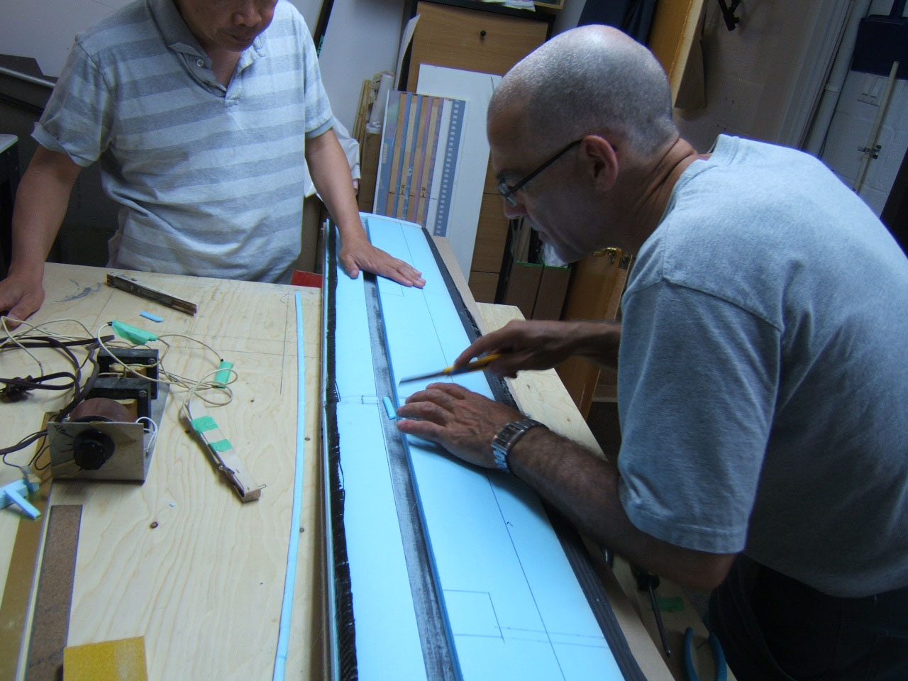

Wing central panel - Step 1 30 June 2010 The wing skin of the central panel has been draped by Stephen and Jacques. Everything went well and the result is excellent. Look at the shiny finish and precise fiber position. Nice job guys! 
The first complete fuselage comes out of the assembly line! 26 June 2010 The first fuselage is assembled with tail fins, winch hook and all the supports for radio gear. Stephen could not wait to enjoy the look of a complete glider built with this fuselage and fit one old 4m wing on it Very nice looking glider!!! 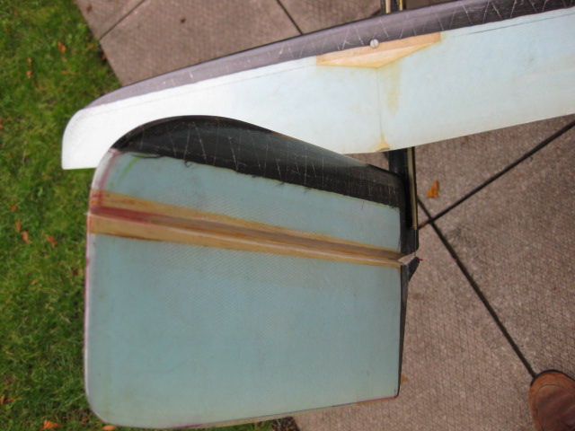
Wing cores 8 May 2010 MATS acquired a CNC Hot-wire cutting machine from Mark Gervais. The machine has been setup with a brand new PC and updated software. After a few trials and tweaks the cores for the Kuda wings have been cut. The precision is outstanding! 

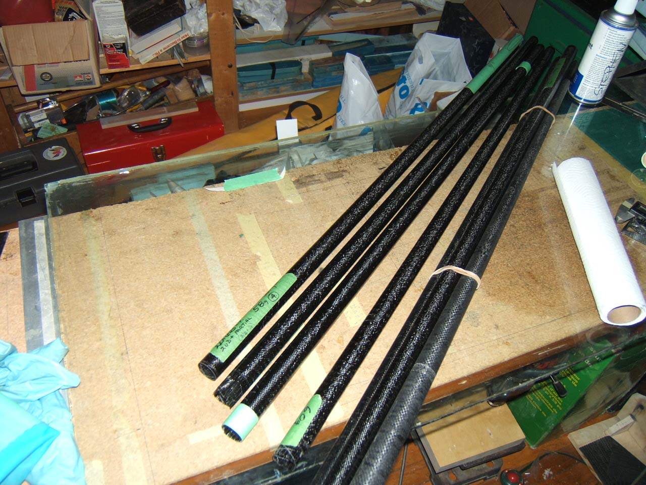
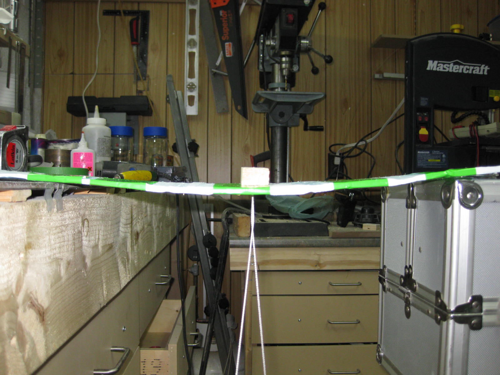
Boom & V-Mount - Testing May 2010 The booms have been tested with a 20 lb load applied at the extremity. Boom and V-Mount have so far proven to be up to the task on all departments! 
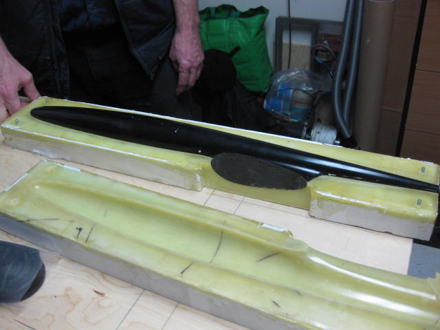
First fuselage 18 April 2010 The first fuse has been taken out of the mould. A wise combination of glass, kevlar and carbon fiber cloth for a 2.4GHz friendly fuselage. Some minor defects over the pylon area but already a very good weight to stiffness ratio. As a matter of fact the weight is equal to the original Supra but our design is a little larger...I don't know how Steve can squeeze so much resin out of the layup, kudos to him!!! 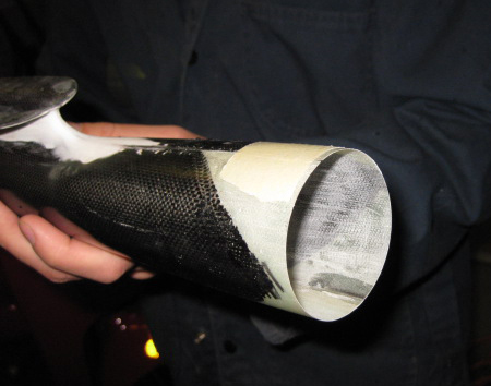

Wooden ribs, servo mounting plates & CO 31 March 2010 The appetite comes by eating...the laser cut machine works perfectly therefore we have generated the .dxf files and cut the rest of the components. All the ribs and the servo mounts have then been assembled. Sweet!!! 


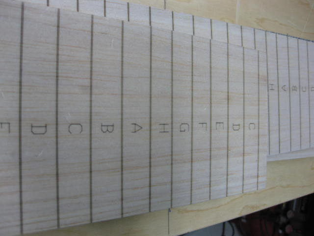
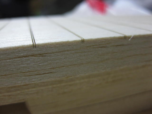
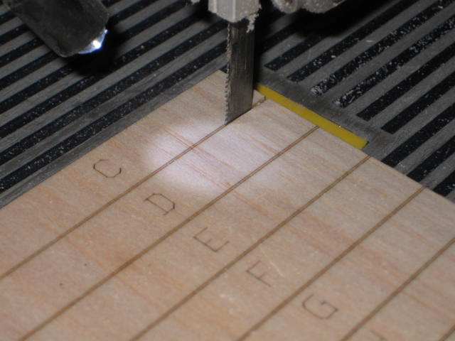
Wing Central Panel Spar 23 March 2010 Flanges have been realized curing strips of pre-cured 0.007" thick carbon UD. Webs are balsa made. Jacques has found a source for laser cutting wooden parts: balsa planks have been scribelined so that cutting is now a piece of cake. 
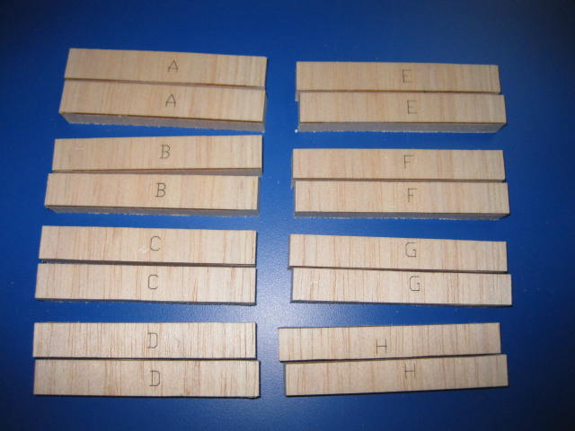
Webs and flanges have been epoxied together with the wing joiners afterwards. 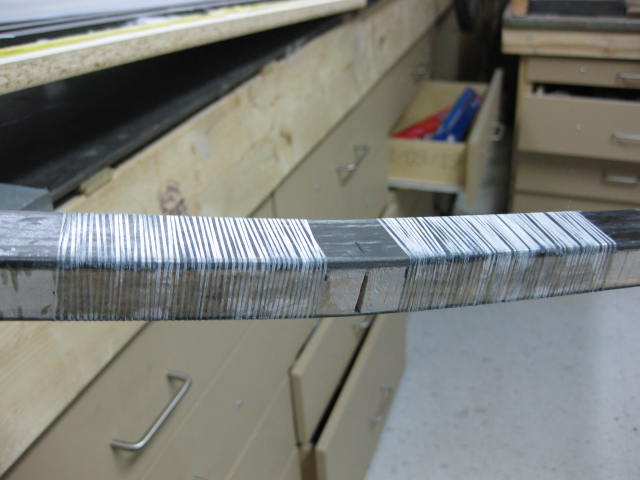
The central portion of the spar has been wrapped and a carbon sox has been put over the whole thing. 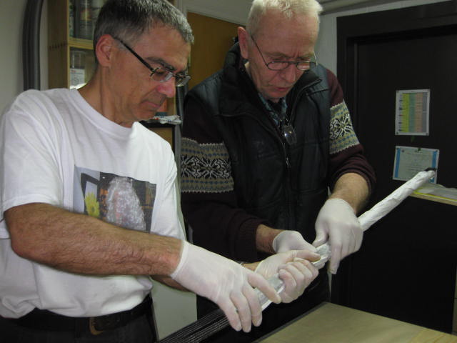
The spar comes out of the bag at the weight of 290gr. 
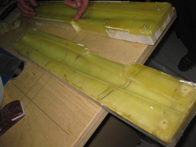
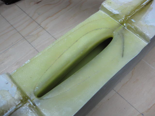
Fuselage Master & Mould - Polishing 19 March 2010 The plug for the mould is wooden made, painted and polished by Stephen. The mould is split for de-moulding, because of the geometry of the pylon. The surface is shiny and flawless and the mould is really robust...no distortion whatsoever with such a brick! 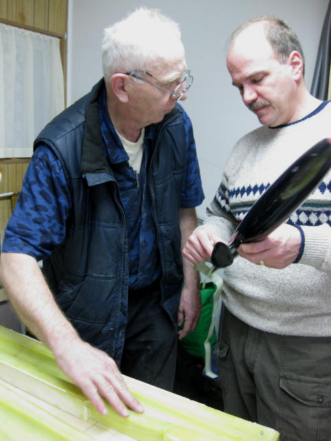

Fuselage Master & Mould March 2010 The plug for the mould is painted in black so that any surface defect can be picked up and corrected. 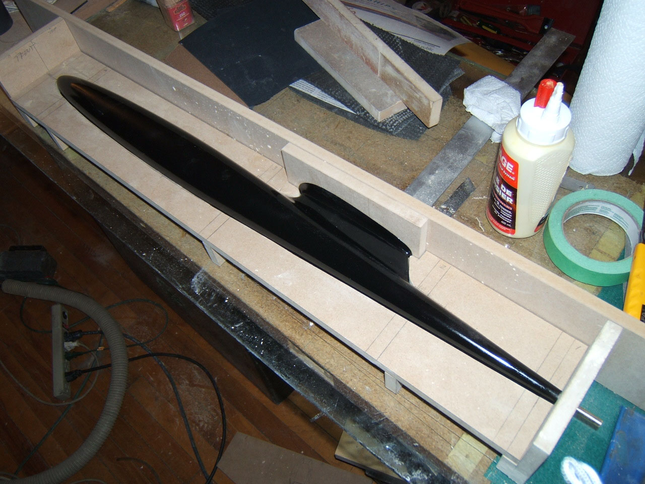
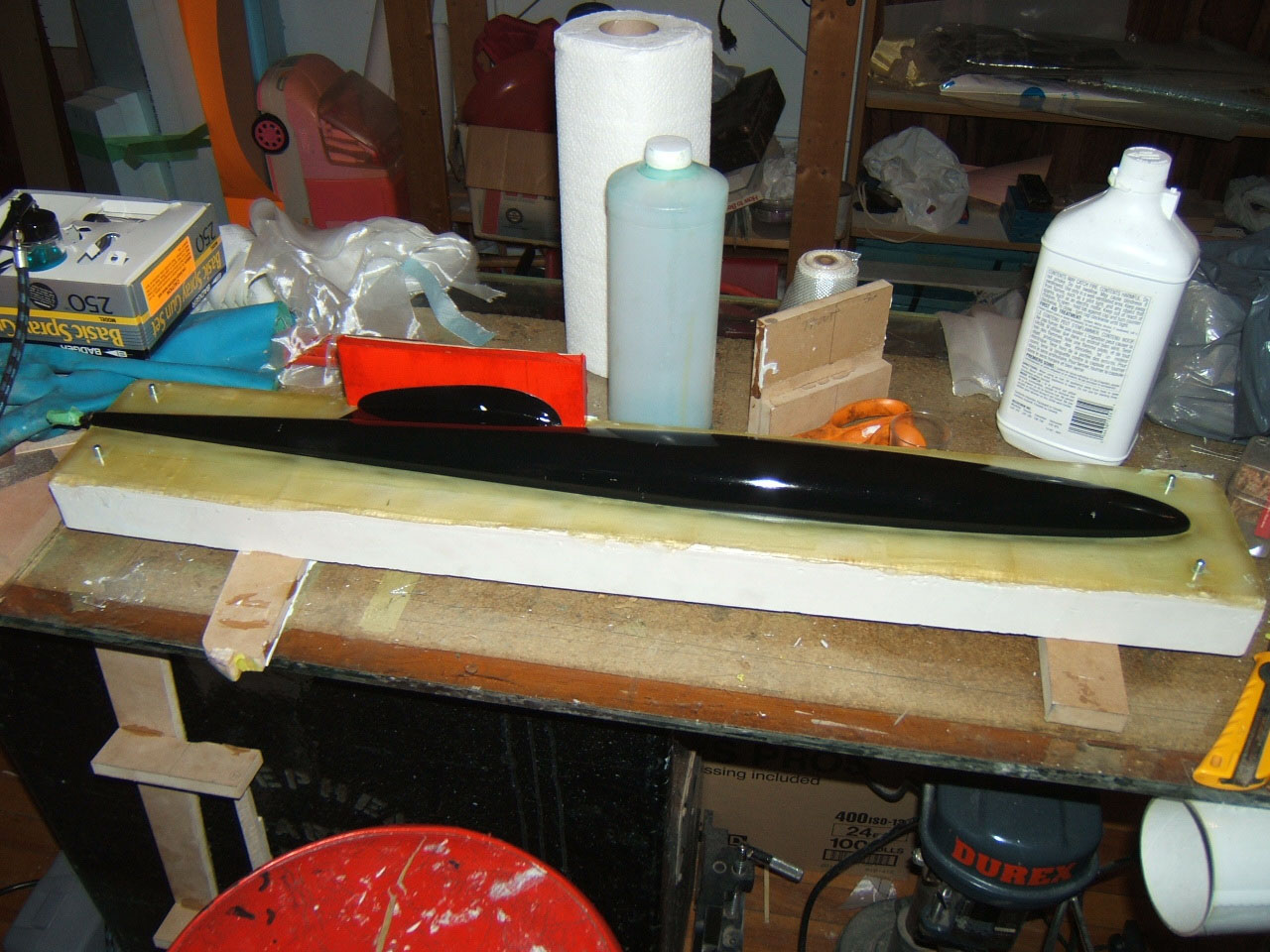
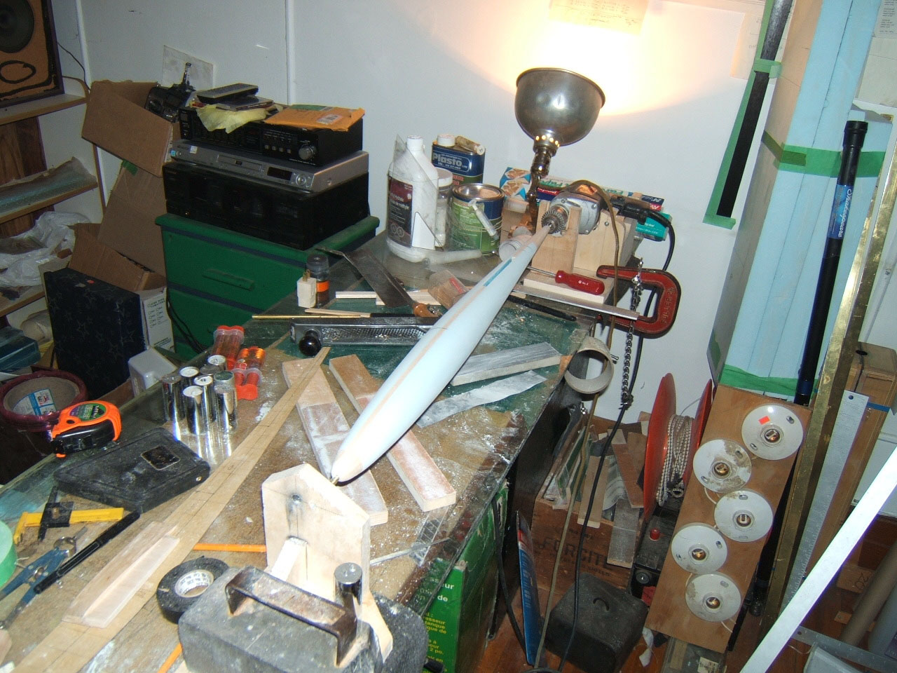
Fuselage Plug February 2010 Some pictures of the fuselage plug preparation. The secret? A lot of sanding...visual checking...spackling...sanding...visual checking...spackling...sanding...keep going!!! 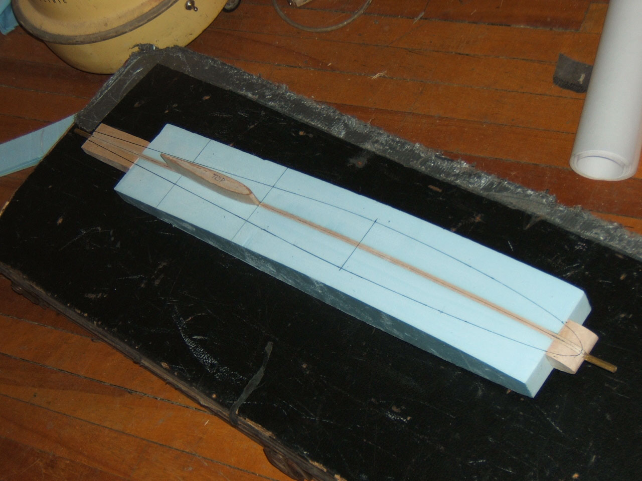
V-Mount 24 Jan 2010 Jacques has put together a mould for the V-Mount and produced a series of V-Mount based on his experience with the Allegro V-Mount. Once again very nice job! 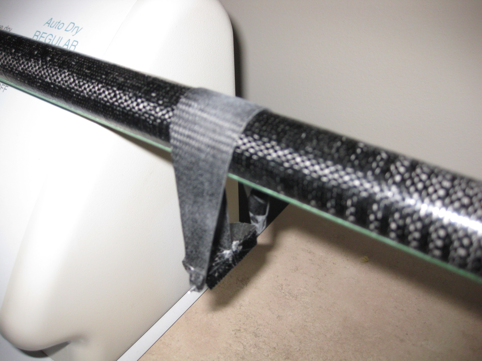


HStab test 23 Jan 2010 The H-Stab has been redesigned following a catastrophic failure at the first load test. A new configuration for the Spar has been found and tested. We now have a carbon tube as a spar and the test shows compliance with more than 20lb applied in the middle section. Some HStabs have been already built with glass skins. New HStabs will probably have Kevlar skins. 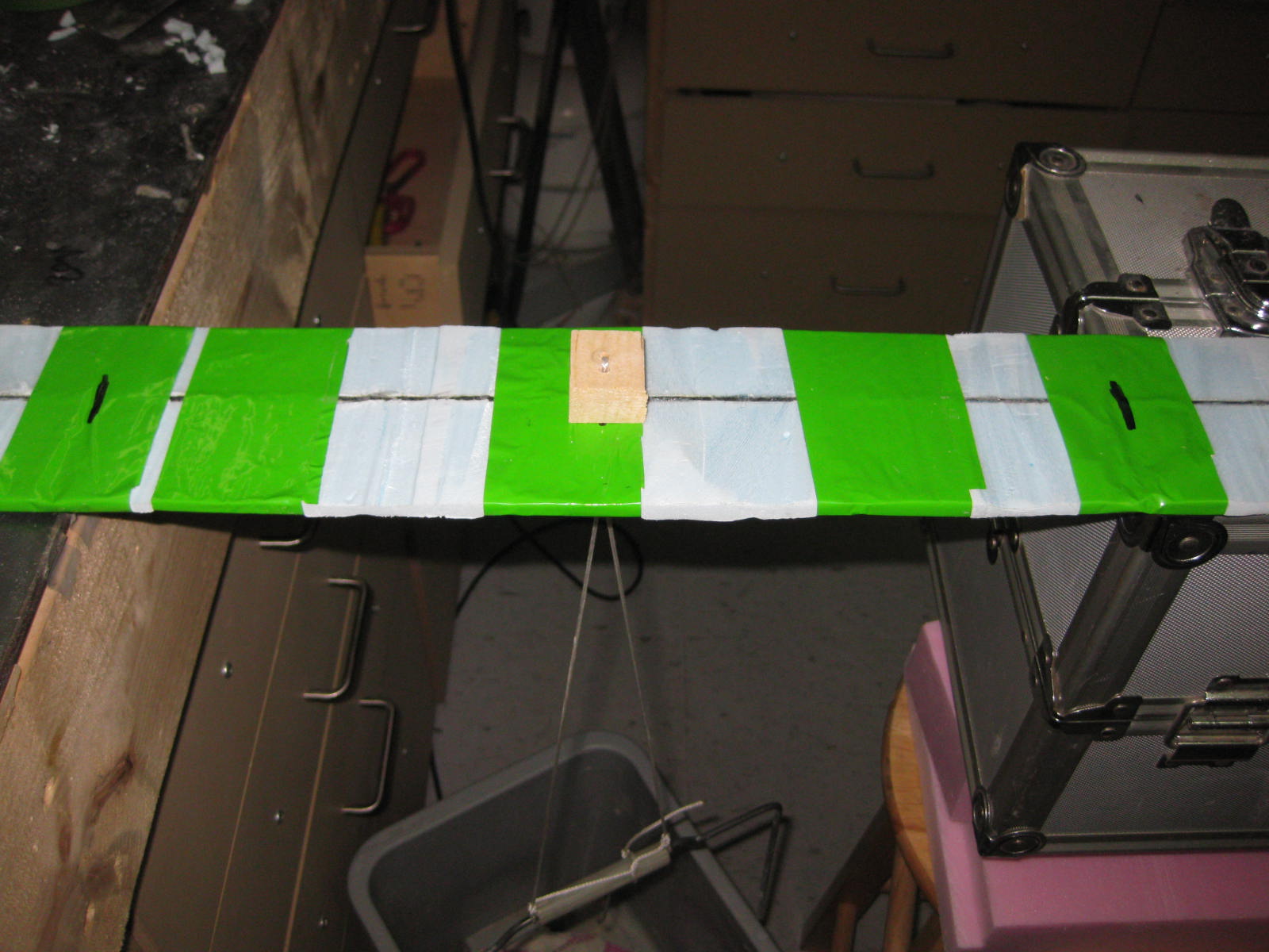
The idea... 5 Jan 2010 The project started very smoothly. After flying many TD competitions, a lot of pilots was discussing about how these new very light and very beautiful moulded models have changed completely the way we fly Thermal Duration nowadays. Nevertheless, these new machines are somewhat fragile, often expensive, and, especially if you live so far from the manufacturers in the New World, very difficult to obtain. Well, let's put it this way: if you then put together the craftmanship of Steve Barry, the energy and managerial push of Jacques Girard, the incredible and never ending source of information from all over the world namely Duc LeVan, and the design skills of your very Italian Luca, you basically kick-off a brand new, Supra inspired project for a big big model. The project has been presented to the MATS AGM 2009 and we hope new enthusiasts will join the team soon to build more gliders with us! So, here's the design goals: 1. The model has to be big (minimum wingspan 3.8m, the bigger the better!) 2. The model has to be strong (Luca's zooms wanted!) 3. Aerodynamic design must be first of all reliable (fly by yourself Baby!) 4. The model has to be easy to be manucfactured (bagged wings, no expensive building techniques!) 5. Who said extra light? (if you need ballast all the time, put that weight into the structure!) 6. The Fuselage, H stab and Central Wing Panel should be common between "short" and "long" version (Keep It Simple!) Wing design The benchmark is certainly the Supra. A first wing planform has been sketched and Reynolds numbers have been calculated based on a weight target (i.e. 2Kg-2.5Kg) way higher than the Supra (1.4Kg-1.8Kg). By instance at the root section the Sq(Re) range is 110K-130K versus 98K-110K of the Supra. One can have a look at the final configuration of the 3.8m and 4.0m hereby: 
The root section of the Supra is scarily thin being 8% thick only. A thicker section would give higher bending stiffness properties, reducing tip deflection, but with which aerodynamic penalty? XFoil has been used to check if a thickened Ag40 would be the airofil of choice. As shown in the picture hereunder, a thicker airfoil shows better performances at mid to high Cl,while the thinner section seems being less draggy at the low Cl. A quick estimation of a full wing (induced drag approximated using Cl2/(Pi * AR) being AR = 20) has been performed too, showing that eventually the penalty is very reduced. The curves are so close that we can even claim we have a little advantage against the original section (after all "you believe in what you want to believe"...isn't it? :-D). It is no surprise really, thicker airfoils are more tailored for higher Re! 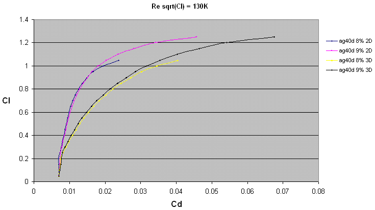
Similar studies have been performed leading to the conclusion that the weight increase basically shifts outboards the optimal airfoil for each section of the Supra wing. Therefore the airfoils of the SupraKuda are Ag40d-9 (being the AG40d thickened to 9%), AG40d, Ag41d and Ag42d (the last three being kept at the original thickness). You can find the templates for those sections hereunder: AG40d-9% AG40d AG41d AG42d H Stab In order to use the same stabiliser for both 3.8m and 4.0m wings, a compromise has to be found. A generous Tail Volume (i.e. 0.4) has been targeted for the 3.8m version giving for the bigger version a Tail Volume of 0.37. The same Lh = 37in (i.e. distance between the 25% of the MAC of the wing and the stabiliser) is used so that the same fuselage can be flown with both wings. The final configuration for the H stab is the following. H Stab Planform The airfoil chosen for the H Stab is a 8% thickened version of the HT14. The thicker section is far easier to build than the original airfoil. Being thicker is also stiffer in terms of bending and torsion. We basically traded some aerodynamic advantage for ease of build and robustness. Here's the results: H Stab Airfoils Templates |
| Last update 17 September 2012
|
||
| Contact the
webmaster |